Writing A Blueprint
A Cloudify blueprint is a YAML file with definitions of resources and connections between them. The syntax is based on the TOSCA (Topology Orchestration Specification for Cloud Applications) specification. It is well-suited to enable multi-domain service orchestration based on Ansible, Terraform, AWS CloudFormation, Azure ARM, Kubernetes manifests, Helm, and a variety of other tools.
In this guide you will learn the basic steps for building service automation using the Cloudify blueprint. The guide is broken down into the following high-level sections:
- Blueprint syntax and structure
- Nodes and resources
- Relationships
- Service composition
To simplify this exercise, the examples in this guide run on the local Cloudify manager instance and do not require any cloud credentials or external dependencies. The process for running the examples is shown at the end of this document in the “Running the examples” section.
If you are interested in learning how to build a Cloudify blueprint to run Ansible, Terraform, or Kubernetes-based services across a Multicloud infrastructure, refer to the relevant section in the Getting Started guide
Blueprint syntax and structure
The simple blueprint example below can be used to illustrate the most basic blueprint structure:
tosca_definitions_version: cloudify_dsl_1_3

description: >
  Input and outputs - describing the most basic blueprint structure

imports:
  - https://cloudify.co/spec/cloudify/6.3.0/types.yaml

inputs:
  hello:
    description: Say Hello to
    default: World

node_templates:
  MyResource:
    type:  cloudify.nodes.ApplicationModule
capabilities:
  hello:
    value:  { get_input: hello }
The remaining parts of this section will walk you through each piece of the blueprint.
Description
description: >
  Input and outputs - describing the most basic blueprint structure
The description section is used to provide a free text field to describe the purpose and usage of this specific blueprint. The description will appear in the blueprint catalog within the Cloudify manager UI.
Imports
imports:
  - https://cloudify.co/spec/cloudify/6.3.0/types.yaml
The import section imports the relevant resource provider libraries, such as plugins, that will be used in this blueprint.
Cloudify includes many resource provider libraries, which are called plugins in Cloudify terminology. These plugins include support for cloud infrastructure resources, such as AWS, Azure, and GCP. They also include support for Ansible, Terraform, AWS CloudFormation, Azure ARM, Kubernetes, and more. You can find the full list of plugins here:
You can also develop your own plugins and add them to a blueprint. You can find more information about custom plugin development here.
Inputs
inputs:
   hello:
    description: Say Hello to
    default: World
The input section defines the arguments that a user can pass and are needed to run the blueprint. An input can have a default value which will be used if no value is provided. An input can also be constrained to ensure that the provided value is valid and will be shown as a drop-down list in the UI.
Capabilities
capabilities:
   hello:
    value:  { get_input: hello }
The capabilities section exposes the relevant resources to the outside world. A capability will often be an API endpoint, website URL or other information that is needed to access the environment. Capabilities can be consumed by end users, such as the user who deployed the blueprint. They can also be consumed by other blueprint deployments.
In this specific example we print the input value using the get_input intrinsic function
Nodes and Resources
The previous example introduced you to a simple blueprint and its high-level sections. Next, you will take a look at a slightly more complicated example so that you can build an understanding of how nodes and resources are modeled in Cloudify.
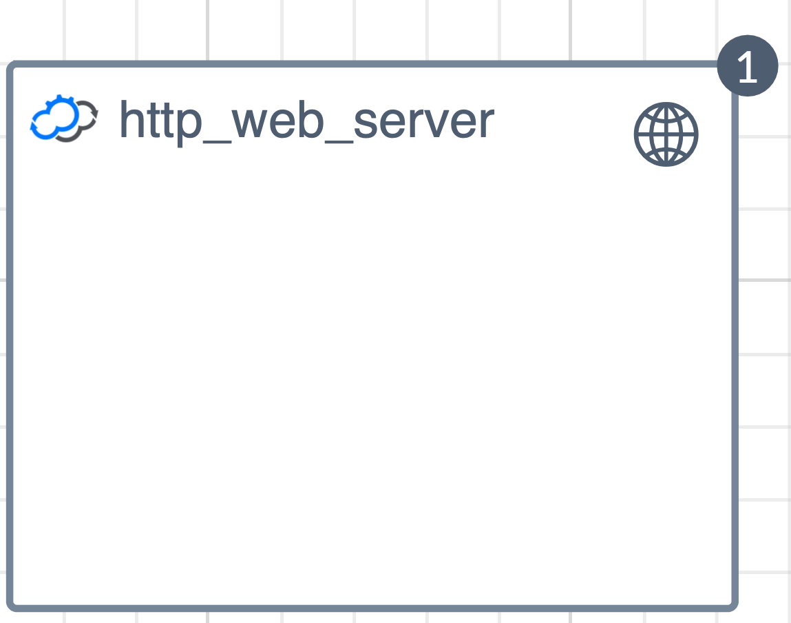
The Hello World example runs a simple web server application locally on the Cloudify manager. It illustrated how you can write a simple service lifecycle operation and execute it using Cloudify. The topology view in the UI is very simple, as this blueprint consists of a single node:
The blueprint file can be found here.
Node templates
node_templates:

  # A node type referencing an http_web_server resource.
  # Implementing the cloudify.interfaces.lifecycle interface as part of the node definition
  # allows us to plug the specific business logic at each point of the lifecycle event.
  # In this example the actual instantiation of the http server is handled by the webserver/start.sh app_script which is called at the [start] lifecycle event
  http_web_server:
    type: cloudify.nodes.WebServer
    properties:
      port: { get_input: webserver_port }
    interfaces:
      cloudify.interfaces.lifecycle:
        start:
          implementation: webserver/start.sh
          executor: central_deployment_agent
        stop:
          implementation: webserver/stop.sh
          executor: central_deployment_agent
The node template section is the main part of the blueprint. It defines the resources in the environment and the lifecycle operation of each resource (node). This blueprint defines a single node, which will be explained in the next section
Node definition
The TOSCA-based node definition is based on an object oriented approach to model resources. As with other object oriented languages it includes interfaces, properties, and supports inheritance.
http_web_server:
    type: cloudify.nodes.WebServer
This example defines a node named http_web_server of type cloudify.nodes.WebServer. The type definition is derived from the import section. In this case we chose one of the built in types. The cloudify.nodes.WebServer type is defined in the types.yaml file.
Note: A simplified way to browse through the definition of each available node types in each plugin would be to use the IDE code completion feature which is supported through the Cloudify IDE Integration)
Most node types are derived from cloudify.nodes.Root, which defines a few interfaces for lifecycle, validation, and monitoring (see below). You can also see that operations can be specified for many different parts of a node’s lifecycle. These operations offer you flexibility when modeling your environment. For example, a web server might be installed during the “create” operation, and the server software may be stopped via the “stop” operation.
cloudify.nodes.Root:
    interfaces:
      cloudify.interfaces.lifecycle:
        precreate: {}
        create: {}
        configure: {}
        start: {}
        poststart: {}
        prestop: {}
        stop: {}
        delete: {}
        postdelete: {}
        pull: {}
      cloudify.interfaces.validation:
        create: {}
        delete: {}
        # Deprecated - should not be implemented.
        creation: {}
        deletion: {}
      cloudify.interfaces.monitoring:
        start: {}
        stop: {}
In the specific example for the http_web_server, we choose to implement only the lifecycle interface with the start and stop operations. The start and stop operations point to the webserver/start.sh and webserver/stop.sh scripts, respectively. These are Python scripts located in the webserver/ directory in the repository. The script path is relative to the blueprint location within the blueprint archive.
Relationships
In the previous Hello World example, we saw how we can model a single node type and execute its lifecycle operation through a blueprint definition. In this example, we will add a NodeJS calculator application as another node type which will be contained in the http web server from the previous example.
We will fetch this application from a Git repository by calling app_scripts/create.sh as part of the create lifecycle event:
   web_app:
    type:  cloudify.nodes.ApplicationModule
    relationships:
      - type: cloudify.relationships.contained_in
        target: http_web_server
    interfaces:
      cloudify.interfaces.lifecycle:
        create:
          implementation: app_scripts/create.sh
          executor: central_deployment_agent
          inputs:
            app_path: {get_attribute: [http_web_server, path] }
            app_git: { get_input: app_git }
        delete:
          implementation: app_scripts/delete.sh
          executor: central_deployment_agent
          inputs:
            app_path: {get_attribute: [http_web_server, path] }
For this purpose we will add a relationship section to the node definition:
  relationships:
      - type: cloudify.relationships.contained_in
        target: http_web_server
The cloudify.relationships.contained_in will tell Cloudify to run the lifecycle operation of this node type on the same host that was created by the http_web_server node above
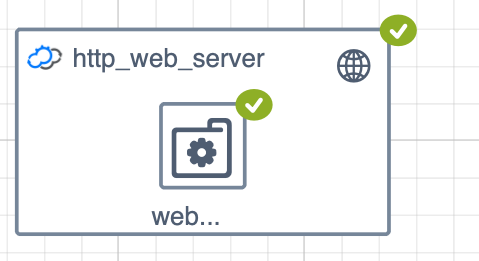
This also means that this web_app node will run only after the http_web_server has been deployed successfully. The topology view reflects the addition of the new node within the http_web_server:
The full blueprint file can be found here.
The relationship is an object of its own and represents a lifecycle operation that is triggered when the relationship is established. For example: a relationship can be expressed between a server and a load balancer. When this relationship is established, a REST call might be executed to add a server to the load balancer
There are a few built in relationships such as depends_on connected_to and contained_in. Each plugin can also define a custom relationship implementation.
Service composition
The previous examples focused on a single blueprint. The Service Composition example illustrates how you can create a multi-tier or distributed service where each service will have an independent blueprint and lifecycle operation. This concept is similar to application microservices, with a clean separation between discreet components. We will illustrate how we can create dependencies and relationships between services, pass inputs and outputs between services, and combine multiple blueprints into a single environment.
The ability to combine multiple blueprints into a single environment is referred to as Service Composition. The Service Composition node type allows us to wrap an external service and expose it as a local node type. This allows us to leverage blueprint features, such as relationship and dependency management, between multiple blueprints just as you would with a regular blueprint.
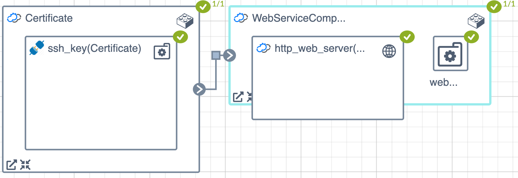
The diagram below shows the parent blueprint topology. The Certificate and WebService are ServiceComponent node types. Each points to a child blueprint.
Notice that the service component node types have a “Lego” building-block in the top-right corner of their icon. This indicates that this specific node points to another blueprint. The arrow and cross icons at the bottom left of the node allow you to zoom in and out, or view the underlying child blueprint behind each component.
Blueprint description
A service component is a special node type that can point to an external blueprint and expose it as local node type to the parent blueprint.
WebServiceComponent:
    type: cloudify.nodes.ServiceComponent
    properties:
      resource_config:
        blueprint:
          external_resource: False
          id: ex3-relationship-blueprint
          blueprint_archive: { get_input:  blueprint_archive }
          main_file_name: ex3-relationship-blueprint.yaml
        deployment:
          id: ex3-relationship-blueprint
The resource configuration provides information that will allow Cloudify to create a deployment resource on demand. There are two approaches for this process:
- Creating a deployment from an already uploaded blueprint:
      resource_config:
        blueprint:
          external_resource: True
          id: ex3-relationship-blueprint
        deployment:
id: ex3-relationship-blueprint- Uploading and installing a blueprint on demand. If the blueprint isn’t already loaded in the manager, it can be uploaded on demand using the
blueprint_archiveandmain_file_nameparameter. These parameters point to the ZIP archive containing the blueprint and the main blueprint file name, respectively.
      resource_config:
        blueprint:
          external_resource: False
          id: ex3-relationship-blueprint
          blueprint_archive: { get_input:  blueprint_archive }
          main_file_name: ex3-relationship-blueprint.yaml
        deployment:
          id: ex3-relationship-blueprint
The full blueprint file can be found here.
For a more advanced use case of service composition see the Multicloud NodeJS example which illustrates how you can use this capability to run the same NodeJS application across different cloud and infrastructure orchestration tools. In this case we use the service component to decouple the application service from the infrastructure and allow the user to choose the infrastructure that best suits their needs. The EaaS example illustrates how you can use service composition to optimize development and production environment stacks.
Running the examples
The examples from this article can be easily run on your local Cloudify manager.
First, download the blueprint archive from the community Github repository. The [source code] (https://github.com/cloudify-community/blueprint-examples/tree/master/introduction-to-blueprints) is also available.
To run the first example demonstrating basic blueprint structure, use the following command:
$ cfy install -b Example-1 -n ex1-input-output-blueprint.yaml introduction-to-blueprints.zip
Once the installation has succeeded, inspect the deployment from the UI or CLI. Uninstall the example before moving on to the next example:
$ cfy uninstall Example-1
To run the second example demonstrating the addition of node templates, repeat the same process with the second blueprint file:
# Upload the blueprint and create a deployment in a single command
$ cfy install -b Example-2 -n ex2-node-type-blueprint.yaml introduction-to-blueprints.zip

# Inspect the deployment via the UI or CLI. For example, to obtain deployment capabilities:
$ cfy deployment capabilities Example-2

# Tear down the example when you are finished
$ cfy uninstall Example-2
To run the third example demonstrating relationships, repeat the same process with the third blueprint file:
# Upload the blueprint and create a deployment in a single command
$ cfy install -b Example-3 -n ex3-relationship-blueprint.yaml introduction-to-blueprints.zip

# Inspect the deployment via the UI or CLI. For example, to obtain deployment capabilities:
$ cfy deployment capabilities Example-3

# Tear down the example when you are finished
$ cfy uninstall Example-3
Finally, to run the fourth example demonstrating service composition, repeat the same process with the fourth blueprint file:
# Upload the blueprint and create a deployment in a single command
$ cfy install -b Example-4 -n ex4-nested-blueprint.yaml introduction-to-blueprints.zip

# Inspect the deployment via the UI or CLI. For example, to obtain deployment capabilities:
$ cfy deployment capabilities Example-4

# Tear down the example when you are finished
$ cfy uninstall Example-4
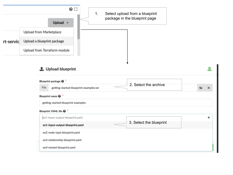
You can also use the web console interface to upload and run the examples:
Summary and next steps
This set of examples introduced some of the core concepts behind the Cloudify blueprint. The most common use case for the Cloudify blueprint is as an orchestrator of orchestrators. A blueprint can contain many different resources based on Terraform, Kubernetes, Ansible, and other tools across a multicloud environment. To learn more on how this is done, refer to the relevant section in the Cloudify Getting Started guide
References
The following resources are helpful for building your knowledge of Cloudify blueprints: