Creating Blueprints
A blueprint is a model of the application’s topology and its operations implementation.
Cloudify Composer allows to display/edit the blueprint in two complementary ways:
- Topology view - visual representation of the blueprint
- Source view - blueprint’s source code
Topology view
It provides visual representation showing used nodes and relations between them. You can access this view by clicking Topology option under the blueprint in Project view pane.
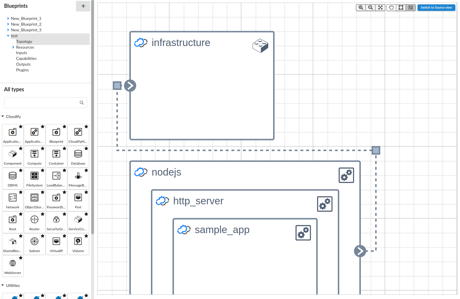
You add and move node types on the canvas using drag and drop actions. The buttons on the top right of the canvas assist you in creating and viewing the topology:
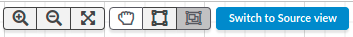
- Zoom in
- Zoom out
- Fit topology to screen
- Switch to drag canvas mode
- Switch to drag to select mode
- Create a group from selected nodes
- Switch to Source view
Nodes types
All node types - both Cloudify built-in and provided by the imported plugins - are presented in the left pane called Stencils pane. Each type is displayed with an icon that is derived from its parent type.
You can also import your own node types by adding plugins. See Managing Plugins on how to add plugins to a blueprint.
Adding Nodes to a Blueprint
Select the node type that you require to add to the blueprint and drag it from the Stencil catalog to the canvas.
Cloudify Composer only allows you to perform valid actions.
Editing a Node
Click the node to display the node property panel. It includes the following components:
- Node Name - The name must be unique.
- Clone (button) - This operation clones the node.
- Delete (button) - This operation cannot be reversed. When you delete a node that is connected to other nodes, the relationship connecting the deleted node is also deleted.
- Node Type - Type of the node.
- Properties - The properties that you see are dependent on the node type. Their values can be edited.
- Interfaces - The interface properties are dependent on the node type. They enable you to specify the implementation for every stage of the node lifecycle. You can reference external plugin implementation for the interface, and also define the list of inputs.
- Relationships - Relationships are only displayed for nodes that are connected to other nodes.
- Network - The networks and networks’ components associated with the current node. For example, security groups and IP addresses. By adding one or more relevant components, you can assign them to the node and also see them reflected in the VNIC square.
To close the panel, press Esc or click the close window icon on the top-right corner.

Setting properties
Each node property has an individual input field for specifying its value. How this value is interpreted can be changed using dropdown field available next to it. By default, entered values are used directly as static, plain values, with exception to Dictionary and List property types, which require valid YAML object and array to be specified, respectively. Depending on the property type this can be changed to one of other options:
- Input - allows using input value as property value (uses
get_inputintrinsic function) - Secret - allows using secret value as property value (uses
get_secretintrinsic function) - Property - allows using another’s node template property as value (uses
get_propertyintrinsic function) - System - allows using tenant name or certain deployment attributes as property value
- Environment capability - allows using existing environment blueprint capability as property value (uses
get_environment_capabilityintrinsic function). When this option is active the value is specified with two dropdowns. The first one selects environment blueprint existing on the Cloudify Manager. The second one selects capability of the environment blueprint. - Capability - allows using component blueprint capability as property value (uses
get_capabilityintrinsic function). When this option is active the value is specified with two dropdowns. The first one selects component node template that is associated with a blueprint existing on the Cloudify Manager. The second one selects capability of the blueprint. - Attribute - allows using node instance attribute as property value (uses
get_attributeintrinsic function). - Advanced - allows specifying any valid YAML as property value
For Dictionary and List types, as well as for Advanced mode it is possible to use intrinsic functions manually. The intrinsic functions list is available at Intrinsic functions specification page.
Cloudify Composer auto-fills the functions and displays the available properties in the existing topology.
Note that, for the get_attribute function you must be familiar with and use the run-time attributes’ names, not the auto-filled properties names.
For example, to obtain a virtual IP address using the get_attribute function, use the run-time attribute VirtualIp_address, not the VirtualIP property.
Service composition related node types provide dedicated features that make defining their properties easier in the context of blueprints and deployments available on the manager.
For cloudify.nodes.Component and cloudify.nodes.ServiceComponent node types when “External resource” flag in “Blueprints” section is turned on it is possible to select one of the blueprints already existing on the manager.
Alternatively, it is possible to manually enter an in-existing blueprint ID.
Once existing blueprint ID is selected and “External resource” flag in “Deployments” section is turned off it is possible to load blueprint inputs and set them as a template for “Inputs” property - inputs’ values are initially set to their defaults and can be further aligned.
Individual inputs can be also removed from the loaded list.
When “External resource” in “Deployments” section is turned on it is possible to select one of the deployments already existing on the manager.
This feature is also available for cloudify.nodes.SharedResource node type when specifying “Deployment ID” property.
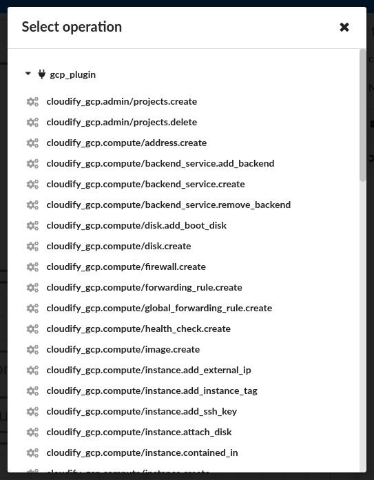
Setting interfaces
To select the operations that you require, click the ![]() icon next to the implementation fields in the node’s Interfaces section on the right of the screen. The following dialog box is displayed:
icon next to the implementation fields in the node’s Interfaces section on the right of the screen. The following dialog box is displayed:
Defining relationships
To define a relationship between nodes, where the connector icon is displayed, draw a connecting line from the edge of one node type to the edge of another. Note that the connector icons show either relationships in or relationships out of a node type.
You can pull the relationship line so that it is displayed in the topology according to your preferences.
Click a relationship connector to display its properties for editing and configuring the relationship parameters.
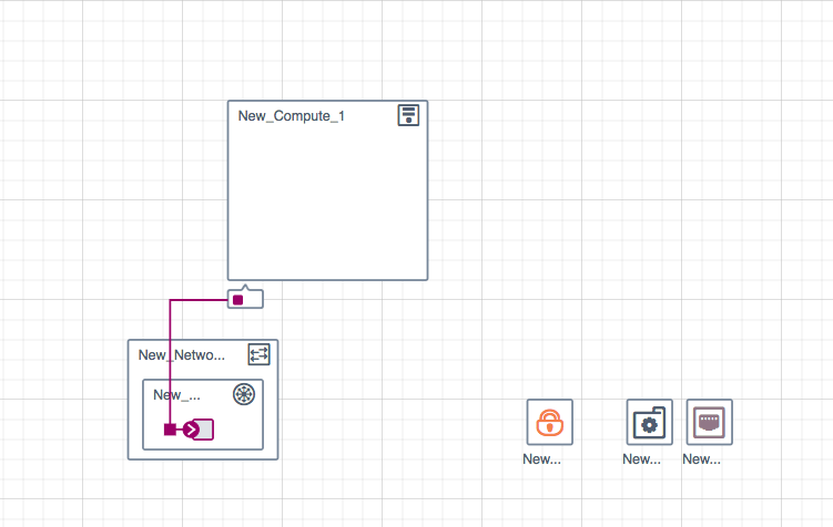
Creating networks
To connect networks, subnets and ports to a platform node, click and drag a line from the VNIC square at the bottom of the node to the left (entry) side of the network. The connection is reflected as a colored square in the VNIC. Each square in the VNIC represents one connected network.
Virtual IP
To define IP components, drag the relevant icon to the topology canvas then select the node to which you want to add the IP.
- In the properties panel, click Network.
- Under the Virtual IPs section, click Add virtual IP.
- Select the required virtual IP from the dropdown list.
The IP component is added to the node’s VNIC area.
To remove a virtual IP associated with a node, select the node from which you want to remove the virtual IP.
- In the properties panel, click Network.
- Under the Virtual IPs section, locate the virtual IP to remove.
- Click the X button next to its name to delete the IP.
You can also delete a virtual IP from the canvas by selecting it and clicking Delete in the properties panel. It is removed from all nodes on which it was configured.
Security Groups
To define a security group drag the relevant stencil to the topology canvas then click the node to add to the security group.
- In the properties panel, click Network.
- Under the security groups section, click Add security group.
- Select the security group to add from the dropdown list.
To remove a security group associated with a node, click the node from which you want to remove the security group.
- In the properties panel, click Network.
- Under the Security Groups section, locate the security group to remove.
- Click on the X button next to its name to remove the group.
You can also delete a security group from the canvas by selecting it and clicking Delete in the properties panel. It is removed from all nodes on which it was configured.
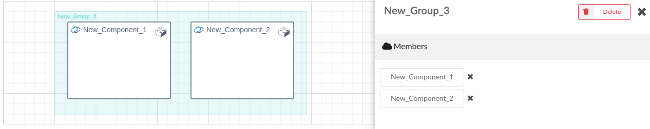
Creating a Group
You can group a number of components using the  button. Select the required nodes and click on the
  button to create a resource group in the Topology view.
The resource group is also created in the source code. You can click the group to display its properties and add or remove members.
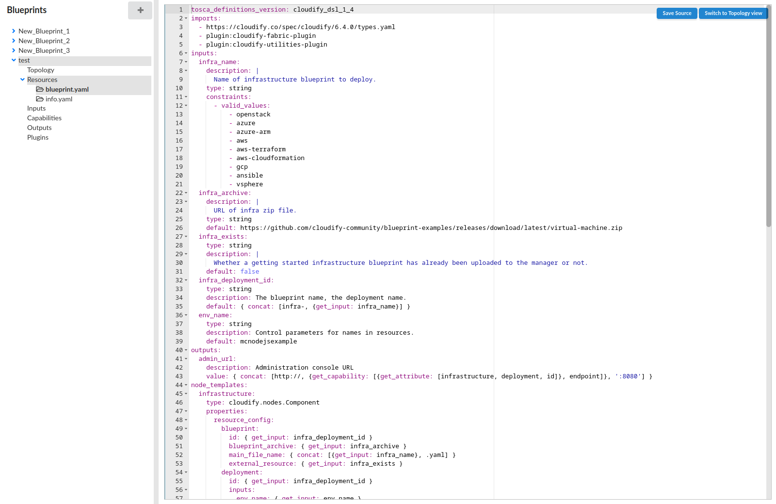
Source view
Source view provides a representation of the generated TOSCA code behind the application modeling. You can open this file in two different ways:
- By manually selecting your main blueprint YAML file under Resources node. The file is highlighted in bold.
- By pressing the Switch to Source view button in the top right corner of the editor.
It works two ways:
-
Allows to see the currently generated blueprint based on all of the user inputs:
- TOSCA definitions version
- imports
- blueprint description
- inputs and outputs
- custom node/relationship types created by user
- nodes added to topology, including their properties, interfaces, network configuration and relationships between nodes
-
Provides a possibility to edit or paste the blueprint source code directly. Cloudify Composer will parse it and reflect in the Topology view accordingly.
Saving resources
To save a modified source press the Save Source button in the top right corner of the editor. Cloudify Composer will then run a 2-step validation:
- Syntax of your source code
- Cloudify DSL rules validation
Switching views
To switch to topology view press the Switch to Topology view button in the top right corner of the editor. Please note this button is available only for main blueprint file and is absent for other files.
If you write some illegal code, it will either not be reflected in the topology and anywhere in the Cloudify Composer or will throw an error.
When referring to any resources in your source code make sure you’ve added them in the main blueprint’s YAML file code.