Cloudify Composer
Cloudify Composer is an editor for creating Blueprint YAML files dynamically, using a drag and drop interface.
Cloudify Composer enables you to model topology for complex applications, and to add relevant lifecycle operations implementation by importing plugins and scripts, or packaging them with the blueprint itself.
Among its drag-and-drop components are platform and network items such as compute node, database, web server, and so on. You can also add your own custom node type components, custom plugins and interfaces.
The generated output from Cloudify Composer is a downloadable TGZ or ZIP archive containing a blueprint.yaml file that provides a TOSCA-based description for the application topology and its lifecycle management. In addition to YAML artifacts, the blueprint archive includes a blueprint package that contains multiple resources such as configuration and installation scripts, code, and basically any other resource you require for running your application.
Logging In
Cloudify Composer is part of the Cloudify Manager premium package and uses the Cloudify Manager user definitions.
To access the Cloudify Composer login screen, browse to http://cloudify-manager-ip/composer or https://cloudify-manager-ip/composer. You must log in using Cloudify Manager credentials.
If you are already using Cloudify Manager Cloudify Console, you can click the ** Cloudify Composer** button in the Local blueprints screen.
When you have logged in to Cloudify Composer, the default Topology page is displayed, with an empty blueprint for your use.
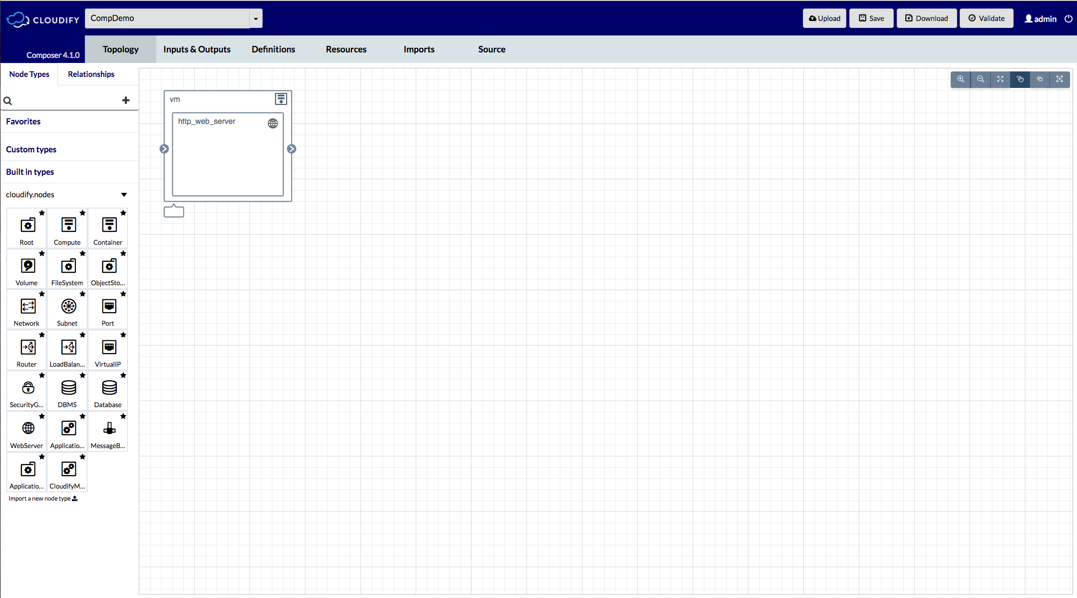
The left side of the Cloudify Composer Topology tab displays a Stencils pane that contains node types that can be used as the building blocks of the topology. The main pane on the tab is a canvas on to which you can drag and drop nodes and define the relationships between them.
You can click the Star icon in any node type in the Stencils pane to mark it as a favorite and move it to the Favorites section of the Stencils pane.
Workflow
This section describes the main functions related to creating a Blueprint. Typically, when you are using Cloudify Composer, your workflow will follow a similar order to that described in this section.
Adding Node Types
Before you start to design your blueprint, you will typically want to add the stencils that contain the basic node types that you need to work with, and the operations that they expose. For more information about node types, click here.
Cloudify Composer supports two methods for adding node types to your Stencils catalog, by importing stencils (for existing node types) and by adding custom node types.
Importing Stencils
You can import a .yaml file that contains definitions of multiple node types. These files are referred to as stencils.
Import a Stencil
Click the Imports tab and select one of the following options:
- Select a default Cloudify plugin in the catalog and click Add.
- Click Add new import and specify a URL or local file that you want to add, and click Save.
After you have imported a stencil, it appears in the Imports list and you can see all the node types that were added, in their relevant node type group.
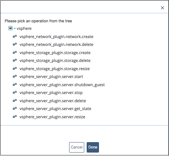
When you add a plugin as an import to Composer, both the nodes types and the operations that the plugin exposes are supported in the blueprint. To select the operations that you require, click the ![]() icon next to the implementation fields in the node’s Interfaces section on the right of the screen. The following dialog box is displayed.
icon next to the implementation fields in the node’s Interfaces section on the right of the screen. The following dialog box is displayed.
Adding Custom Node Types
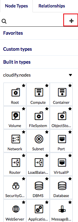
You can add a new node type by clicking the Add icon at the top of the Stencils pane. When you select this option, you must specify the details of the node type that you are creating, for example the node type’s name, parent node type, and so on. You can add new properties and interfaces, or edit the ones that the node type derives from its parent node type.
After you save the new node type, it is displayed in the Stencils pane, under Custom Types. To edit or delete the node type, click the relevant icon at the right of the node type.
Blueprints List
You can display the menu of all available blueprints that you created or imported by clicking the dropdown arrow next to the name of the currently displayed blueprint. The most commonly used blueprints appear at the top of the list. The other blueprints appear in alaphabetical order.
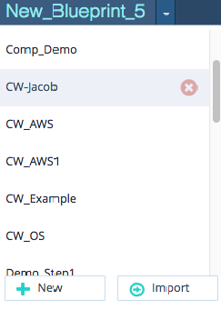
At the bottom of the list are buttons to enable you to create or import a blueprint. To delete a blueprint, hover your cursor over its name and click the X icon.
Importing a Blueprint
To import a blueprint, you must specify the archive that contains the blueprint package (either local or a URL), and the name of the main .yaml file in the package that represents the topology of your environment (in cases in which the archive package contains more than one .yaml file).If the field is left empty, the default is “blueprint.yaml”.
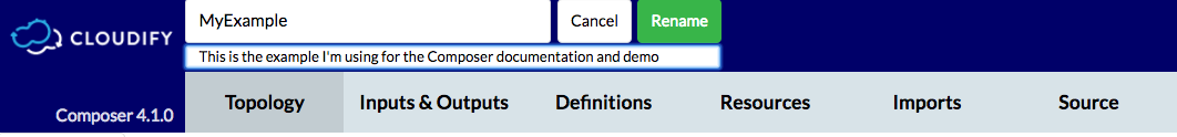
You can click the current blueprint name to edit its name. You can also add a description to the file, which will be added to the .yaml file, and will also appear next to the blueprint name in the list.
Working with Nodes
You add a node by dragging the required node type from the Stencils panel and dropping it on to the canvas. You then click it to edit its properties. The properties that are available are dependent on the node type.
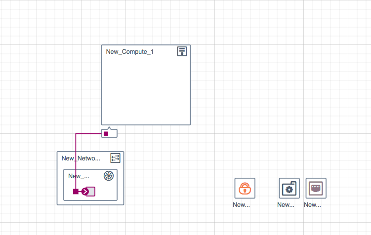
Depending on their type, you can add nodes inside other nodes. For example, a database server can be contained inside a compute node, a subnet node inside a network node, and a port node inside a subnet node. When a node is nested inside another node, a contained-in relationship is automatically generated between them.
You can define other relationships between nodes by clicking, holding and dragging the pointer from the right (exit) arrow of one node to the left (entrance) arrow of another. This action generates a connected-to relationship type.
To connect networks, subnets and ports to a platform node, click and drag a line from the VNIC square at the bottom of the node to the left (entry) side of the network. The connection is reflected as a colored square in the VNIC. Each square in the VNIC represents one connected network.
Adding Plugins to the Blueprint Package
Composer enables you to package plugins together with the .yaml file, so that they are part of the archive that you download or upload to Cloudify Manager. The recommended way to work with plugins is to upload them to the Manager, not to tie them with the blueprint package, therefore you would usually only use this option if you want to use plugins that you have written yourself, or if you have very specific reasons to package them with the blueprint itself.
Adding a Plugin
You add plugins on the Definitions tab. Cloudify supports many plugins, which you can access here. In addition, you can create your own plugins.
Click Add Plugin and specify the following properties:
- The plugin file name
- The Executor
- The URL or a local archive of the specified plugin
Click Save to save the properties that you have specified.
After a plugin is attached to a package, the operations it exposes appear in the interface’s operations implementations tree.
Adding a Relationship Type
Custom Relationships, like types, derive from existing relationships and can also have additional properties and interfaces. Interfaces are defined per the source and target nodes that define the relationship.
Adding a Custom Relationship
- Go to the Relationships tab on the Stencils pane and click the Add icon.
- Specify the required properties and interfaces, and click Save.
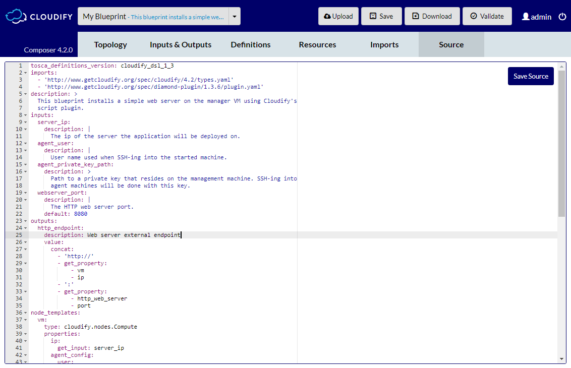
Viewing Topology Source Code
Every addition or change that you make to the topology of your Blueprint package is reflected in code that you can see on the Source tab. This tab provides a representation of the generated TOSCA code behind the application modeling.
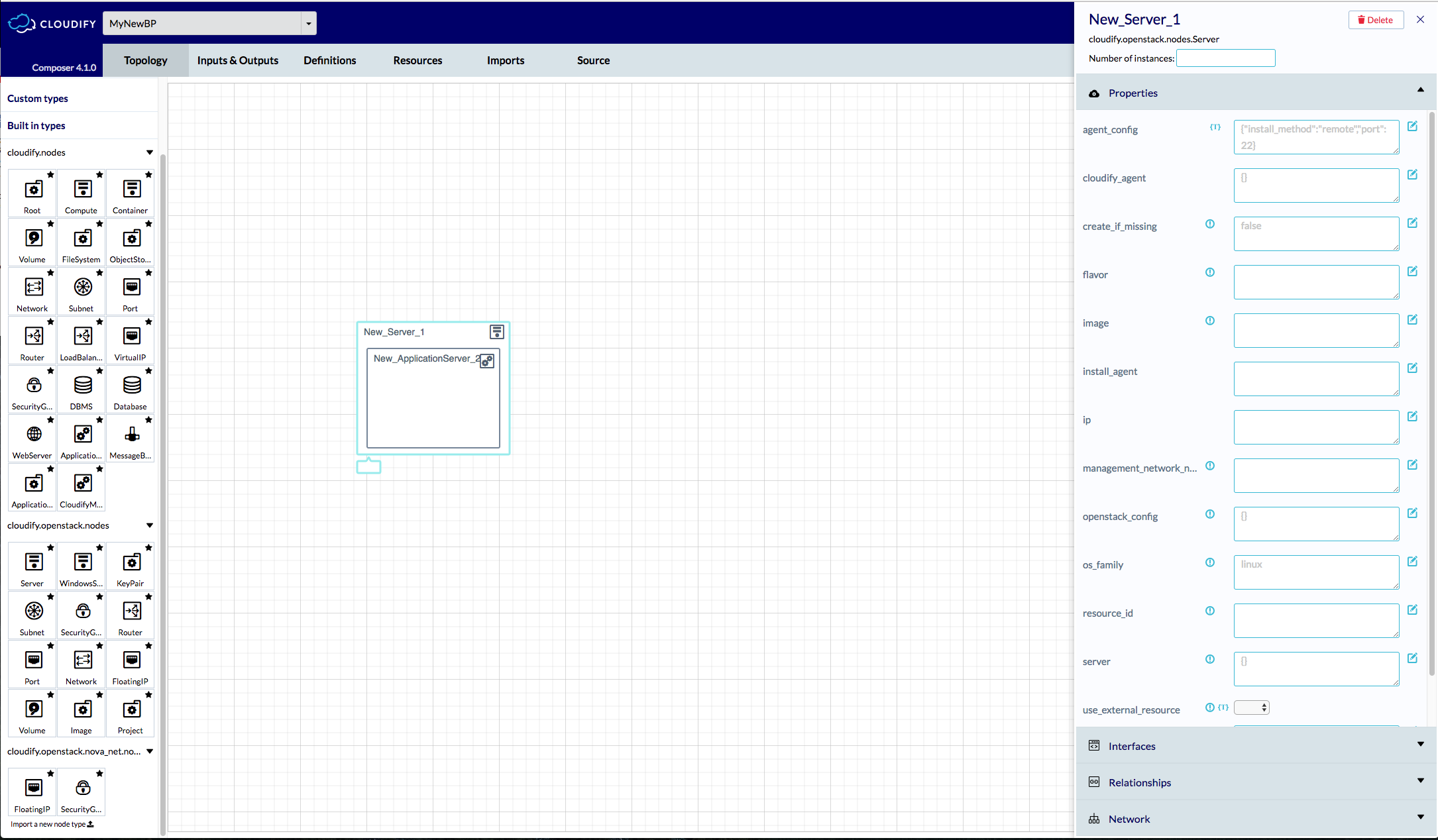
Node Settings
Clicking a node on the Blueprint canvas opens its settings window. The settings are divided into four sections.
Properties: The properties that were defined in the node type or its parents. Their values can be edited.
Interfaces: The interfaces and lifecycle events that are defined in the current node type or its parents. You can select the implementation to occur when a lifecycle operation is executed. You can add a script (that you have previously added to the “resources” tree on the Resources tab), or select a plugin’s operation implementation.
Relationships: The relationships of the current node. You can edit the relationships by clicking on a relationship connector, and changing its settings.
Networks and Network Components: The networks and networks’ components associated with the current node. For example, security groups and IP addresses. By adding one or more relevant components, you can assign them to the node and also see them reflected in the VNIC square.
Intrinsic Functions
As in Cloudify Manager, the values of a node’s properties, inputs or outputs can be specified as intrinsic function return values. The intrinsic functions list is available at http://getcloudify.org/guide/4.0/dsl-spec-intrinsic-functions.html.
Cloudify Composer auto-fills the functions and displays the available properties in the existing topology. Note that, for the get_attribute function you must be familiar with and use the run-time attributes’ names, not the auto-filled properties names. For example, to obtain a virtual IP address using the get_attribute function, use the run-time attribute VirtualIp_address, not the VirtualIP property.
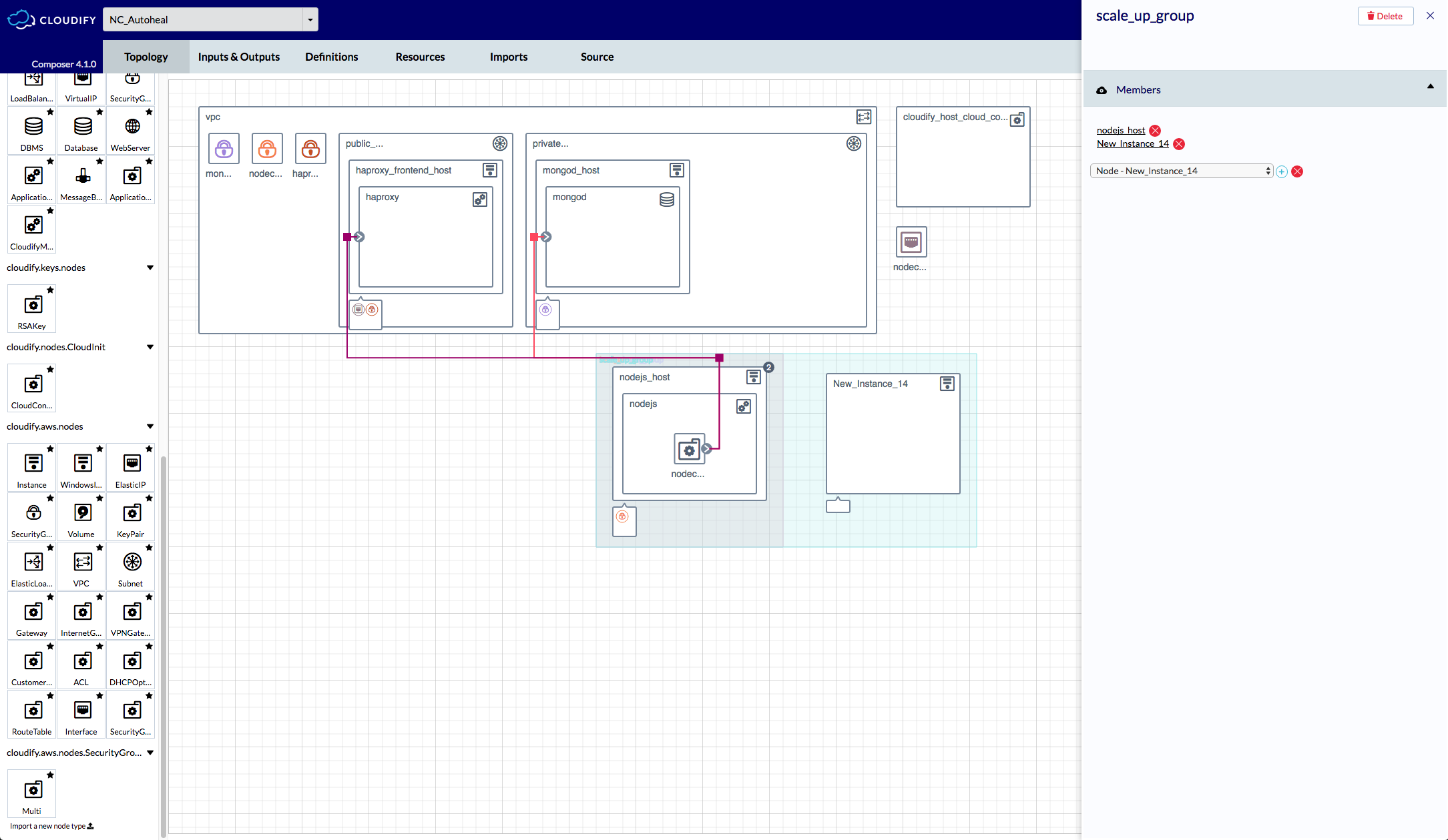
Creating a Group
You can group a number of components using the “drag to select” button  . Select the required nodes and click on the “create group” button
  to create a resource group in the topology view. The resource group is also created in the source code, which you can view on the Source tab. You can click the group to display its properties and add or remove members.
Inputs and Outputs
Cloudify Composer enables you to add inputs and outputs to the Blueprint on the Inputs & Outputs tab.
Inputs are parameters that are inserted into the Blueprint when a deployment is created. They are useful when you need to use information that is still unknown at the time that the Blueprint is created. Inputs can also be used to differentiate between deployments of the same Blueprint. You can reference inputs from other parts of the topology, using the get_input intrinsic function.
Outputs provide a way to expose the global aspects of a blueprint’s deployment, such as the endpoint of a server or other runtime or static information for a specific resource.
Inuputs and outputs can be referenced from other parts of the topology, using the get-input intrinsic function.
Uploading, Saving, Downloading and Validating Blueprints
Use the buttons on the top right of the Cloudify Composer screen to upload a blueprint to Cloudify Manager, or to save, download or validate a blueprint.
Uploading enables you to select to which of the tenants on the Manager you want the blueprint to be uploaded. You can only upload to tenants that your user credentials give you permission to access.
The download operation downloads the last saved blueprint package as a TAR or ZIP archive.
Validating a blueprint reviews the source code, to ensure that logical concepts are valid.