Networking Guide
Getting started with Cloudify networking orchestration
This tutorial covers the steps required to setup your Cloudify Manager and use it to orchestrate the deployment of a network service. It is accompanied by a complete set of ready examples. and structured in a way that walks the reader through the steps required, discusses and explains about alternative approaches and provides references to the actual code used. This tutorial, does not replace the Cloudify documentation, which provides much greater detail on each topic.
Objectives
The objectives of this tutorial are to:
- Get you started with a Cloudify server
- Analyze a basic network service, and orchestrate it using Cloudify through automation of:
- Infrastructure and element provisioning
- Service component configuration
- Chaining all components into a complete network service
- Learn orchestration best practices, and get the basic Cloudify knowledge to get you started with your own deployments.
Prerequisites
This tutorial assumes that the person running it has access to Openstack and/or Microsoft Azure, with the ability to allocate network, storage, and compute instances. Also required is a computer capable of running Docker that has network access to the selected infrastructure. Note that the computer can itself be an instance on the target cloud. The computer/instance requires a minimum of 4GB free RAM, and 5GB of disk storage for the Cloudify Docker container.
Structure
The guide begins with a description of a network service that will serve as the end goal of the tutorial. Next it discusses general VNF and service modeling methodology best practices. Finally, the guide will provide platform specific instructions for applying the methodology by creating an operational service chain using Cloudify.
Analyze our network service example
In this tutorial we are going to use a simple network service consisting of a load balancer and a firewall. To make it a tad more realistic we will be deploying a simple web server to represent the end of the service chain:
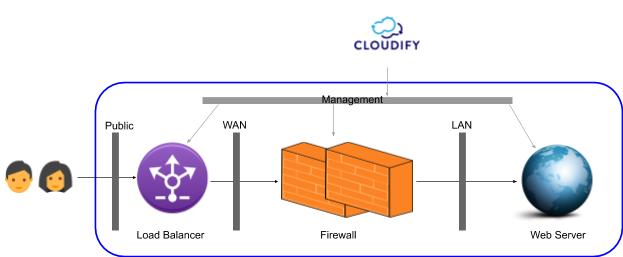
If we break down how one would typically build such a service the basic steps might be:
- Set up the relevant networks
- Provision a firewall and configure its network interfaces and network settings
- Provision a load balancer and configure basic settings
- Provision a web server instance, configure it with basic web content
- Compose the service flow by setting the LB to accept traffic on configurable port, direct it to the firewall, and configure the Firewall to allow web traffic to the web server.
Upon completion of these steps we will have a complete service.
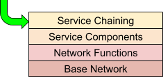
Network Service Orchestration Design Principles
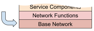
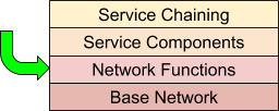
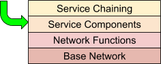
As implied by the previous section, network service orchestration lends itself well to a layered approach. The layered approach makes both the comprehension of the overall system easier, and cleanly fits typical operational requirements. From an orchestration perspective, this means separating concerns that may be dependent on each other, but should be deployed and managed separately. Like the OSI networking model, each layer uses the layer below.
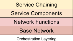
Each layer constitutes a separate orchestration domain, meaning an independent lifecycle. In Cloudify terms, this means each layer consists of a blueprint or blueprints that have relationships to other layers, but are independently operated.
Let’s look at each layer in more detail:
Base Network
This layer is the substrate upon which the VNFs and service components will communicate. This layer itself may be virtualized, and in the context of cloud native orchestration is quite likely to be. The base network for a service chain would include the networks that the service VNFs would attach to, potentially along with supporting VNFs (like virtual routers) that are not part of the service itself. This is the most stable layer, as it serves as the platform upon which many services may be deployed (and undeployed) to over time.
Network Functions
This is the VNF layer. Once the base network is in place, the network functions that comprise the service are deployed. The VNFs attach and communicate via the base network substrate. From the VNFs, potentially many services may be composed.
Service Components
This layer represents non-VNF service components. This layer is optional, as a network service can be pure (say a service that provides packet forwarding). However, many services require non-network elements such as databases, web servers and application servers. The service components utilize the VNF layer to provide the overall service.
Service Chaining
This layer represent service configuration. This layer provides configurations of the underlying network and non-network services in order to provide a specific service configuration. Initial configurations as well as updates are managed at this layer, and rendered to the underlying layers as needed.
Cloudify Example Network Service Design
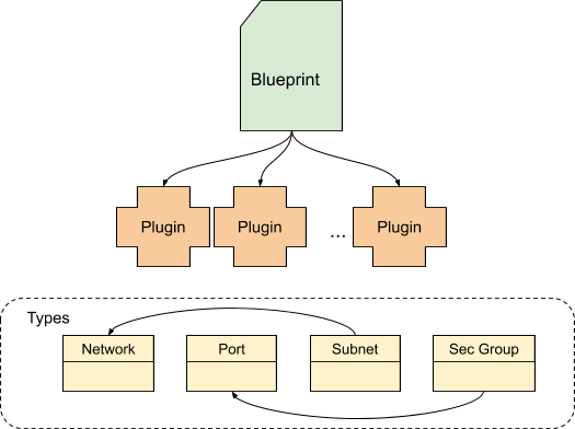
In Cloudify, network services are modeled using blueprints. A blueprint is a general purpose model for describing systems. To model our example network service, a blueprint (or blueprint collection) is created to represent each layer described in the previous section. Blueprints are composed of nodes which are instances of types. A type can represent anything we need to model, but in general represents the things to be orchestrated, virtual or otherwise. For example, a type can represent a network in Azure or in Openstack (or any other infrastructure). In Cloudify, the types are provided as plugins which you include in your blueprints. Once the types are included, they can be associated with each other via relationships.
Base Network
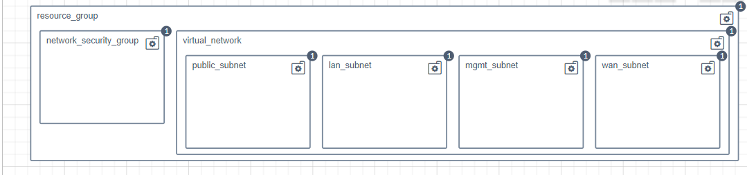
Ignoring cloud specific differences, the goal of the base network blueprint is to create
- A LAN/private network to provide connectivity between the firewall and web server.
- A WAN/public network to provide connectivity between the load balancer and the firewall.
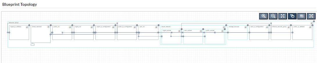
- An external network, to connect the user to the load balancer. These networks, and related items like subnets and ports, are modeled in the base network blueprint using types provided by the plugin specific to your cloud. The details of this layer are exposed to other layers via the capabilities section of the blueprint, which can contain computed/derived runtime values, and is accessible by dependent blueprints.
Azure base network blueprint
Network Functions
For this example, we’ve modeled the VNF layer as a collection of blueprints; one for each VNF (Fortinet Fortigate and F5 BigIP). Each of the VNF blueprints uses information from the previously discussed base network by access it’s defined capabilities. This not only isolates the VNF layer from the lifecycle of the base network, but also permits the VNF layer to consume the base network without being bound to its implementation.
F5 BigIP blueprint
Service Components
This layer is very simple in our example, and consists of a Python web server. It’s purpose is to demonstrate the effectiveness of the next layer, Service Chaining. The service chain deployment will expose the web server by configuring the previously deployed VNFs (firewall and load balancer).
Service Chaining
The final layer is a service chain implemented as a blueprint. This blueprint uses the exposed capabilities of the VNF blueprints to configure a network path that exposes the HTTPD server. This blueprint represents the configuration of the VNFs as separate nodes, and applies the configuration to the existing VNFs using their exposed capabilities and blueprint inputs. Note that there are different service chain blueprints for each platform, however the service chain is independent of the platform. This will be fixed in a future release.
Service blueprint
System & Platform setup
The remainder of the tutorial is a guide to constructing the service chain outlined above.
Available Resources
This tutorial is accompanied by the following resources.
Azure VNF Images
The Azure VNF images are located in the Azure marketplace. The default inputs in the blueprints are sufficient to access them.
Openstack VNF Images
- F5 BigIP (account on http://downloads.f5.com required). The QCOW image is available here. Note that you will need to get a license file to complete the process.
- Fortigate - (account on https://support.fortinet.com needed). The QCOW image is available here (tested with version 6.0.4). Note that you will need to get a license file to complete the process.
Cloudify Manager Deployment
The Cloudify Manager is available in multiple formats ranging from Docker to RPM. In this tutorial we will be using the Docker option and assume that Docker is deployed on your local computer. To learn more about Cloudify Manager deployment go to: Getting-Started (https://cloudify.co/getting-started-enterprise/).
Open your terminal and create/start the Docker container:
docker run --name cfy_manager_local -d --restart unless-stopped -v /sys/fs/cgroup:/sys/fs/cgroup:ro --tmpfs /run --tmpfs /run/lock --security-opt seccomp:unconfined --cap-add SYS_ADMIN -p 80:80 -p 8000:8000 cloudifyplatform/premiumNote that, depending on your user privileges, you may need to prefix the above command with ‘sudo’. If port 80 is unavailable on your host, start the manager with something like ‘-p 8080:80’ rather than ‘-p 80:80’, to make the manager available on a different port.
To access the Cloudify Management Console, go to http://127.0.0.1 (or http://127.0.0.1:
Activate your manager by applying your Cloudify license [This step is required for Cloudify Premium version 4.6 or later]. The license can be applied via the Cloudify Management Console or via the command line. See this page for details.
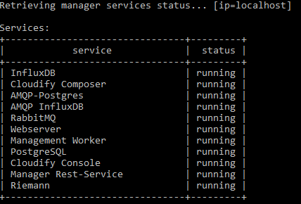
To verify server health from the command line, run docker exec -it cfy_manager_local cfy status. This should produce the following output (as of version 4.5.5):
Plugin Installation
Cloudify has an extendable architecture that uses the concept of plugins for orchestration. Some plugins are built in, and others must be installed based on what platform and components are being orchestrated.
Learn more about plugins.
To install the necessary plugins using the Cloudify CLI, run the following command from the command line:
docker exec -i cfy_manager_local cfy plugins bundle-uploadUploading the plugins takes a few minutes.
Platform API connection parameters
Leveraging Openstack requires access credentials. It is a good practice to keep these credentials as ‘secrets’ in the Cloudify Manager, allowing different deployments to use them without the need to re-mention in every deployment, or exposing them in blueprints.
Openstack API credentials
If using Openstack, you’ll need to create secrets on the manager prior to running the example blueprints If using Azure, skip down to the section following this one. Learn more about secrets…
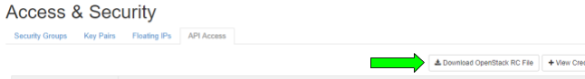
In your OpenStack manager browse to: Compute >> Access&Security >>API Access. Click the ‘Download OpenStack RC file’ option.
Then copy this file to the Docker container like so:
docker cp <your rc filename> cfy_manager_local:envThen run the following commands to upload the secrets:
docker exec -i cfy_manager_local curl -O https://docs.cloudify.co/latest/scripts/upload-secrets.shdocker exec -i cfy_manager_local sh upload-secrets.shAs before, you may need to prefix the commands with ‘sudo’, depending on your account permissions. You will be prompted to enter your Openstack secret during the process.
Azure API credentials
To use Azure you’ll need to create secrets containing API credentials on the manager so the blueprints can use them.
- azure_client_id: Service Principal appId. You can set this up via the CLI:
docker exec -i cfy_manager_local cfy secrets create azure_client_id -s [secret value]. - azure_client_secret: Service Principal password. You can set this up via the CLI:
docker exec -i cfy_manager_local cfy secrets create azure_client_secret -s [secret value]. - azure_subscription_id: Service Principal ID. You can set this up via the CLI:
docker exec -i cfy_manager_local cfy secrets create azure_subscription_id -s [secret value]. - azure_tenant_id: Service Principal tenant. You can set this up via the CLI:
docker exec -i cfy_manager_local cfy secrets create azure_tenant_id -s [secret value]. - azure_location: Specifies the supported Azure location for the resource. You can set this up via the CLI:
docker exec -i cfy_manager_local cfy secrets create azure_location -s [secret value]. - agent_key_private: The content of an RSA private key. (E.g. You can upload this key from a file:
docker exec -i cfy_manager_local cfy secrets create agent_key_private -f ~/.ssh/id_rsa). - agent_key_public: The content of an RSA public key. (E.g. You can upload this key from a file:
docker exec -i cfy_manager_local cfy secrets create agent_key_private -f ~/.ssh/id_rsa.pub).
Provision the service components
Provisioning the base network
The key prerequisite for a VNF deployment is typically a network or more likely a set of related networks. This represents the “base network” layer in the design principles. In our example the Firewall is connected to 3 networks: Management network, WAN and LAN. and we will make sure we set all 3 up before provisioning the VNFs (network function layer).
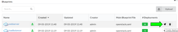
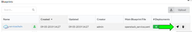
Upload the base network blueprint
Using the Cloudify Management Console from the “Local Blueprints” page, select the “Upload” button.
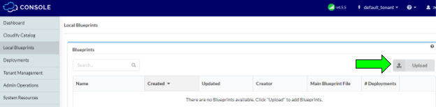
This will display the “Upload blueprint” dialog. Fill the fields in as follows:
- Blueprint package: https://github.com/cloudify-community/blueprint-examples/releases/download/latest/network-automation-example-network-topology.zip
- Blueprint name: service-base-network
- Blueprint YAML file:
- If using Openstack: openstack.yaml
- If using Azure: azure.yaml
Once these fields have been entered, press the “Upload” button to copy the blueprint to the Cloudify Manager.
Create the base network deployment
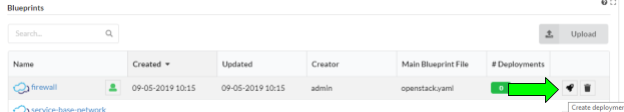
Uploading the blueprint placed it in the Cloudify Manager local repository. In order to run workflows ( e.g. “install” ) on the blueprint, you must create a deployment, which represents the blueprint and any input parameters. From the “Local blueprints” page on the Cloudify Management Console, click the rocket ship icon on the “service-base-network” blueprint line:
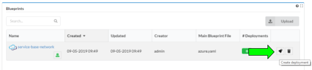
This will display the “Create deployment” dialog box. It is here that the blueprint parameters are entered. Make the following entries:
- Deployment name: service-base-network.
- If using Openstack:
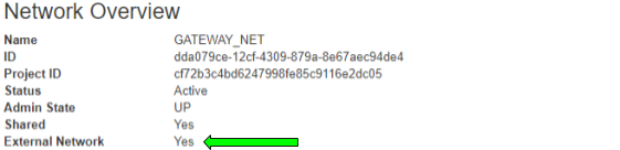
- External_network_name: the name of the Openstack tenant network that provides internet access ( often something like ‘Ext-net’).
If you are unsure about the external network name, look at the network details for the attribute “external: true”, in the Horizon networks page:
Click the deploy button. This will kick off the deployment creation, and we are ready to install the network. If you are using Azure, the defaults in the blueprint are sufficient.
Create the base network
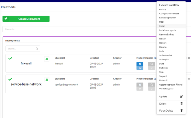
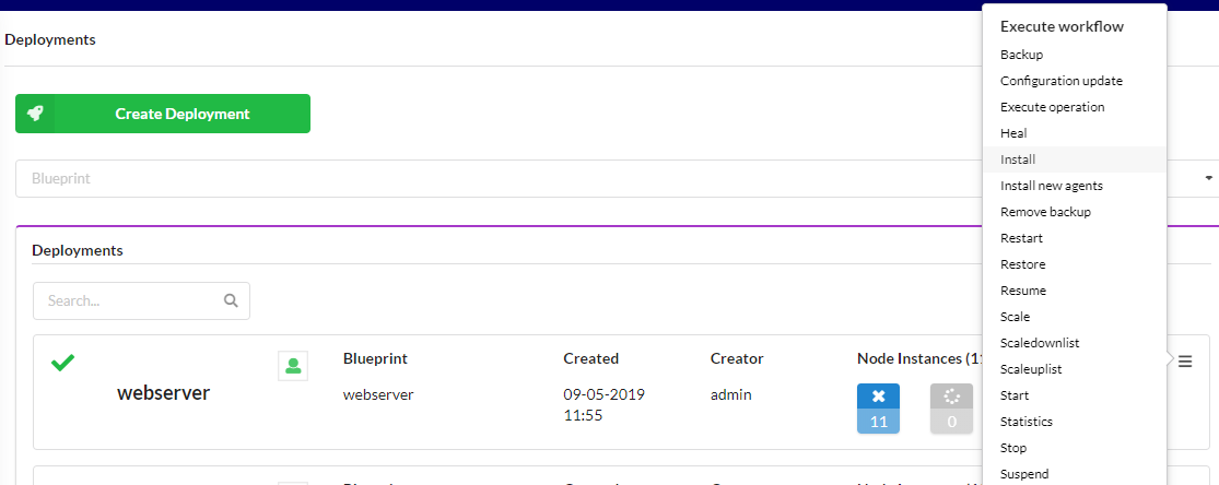
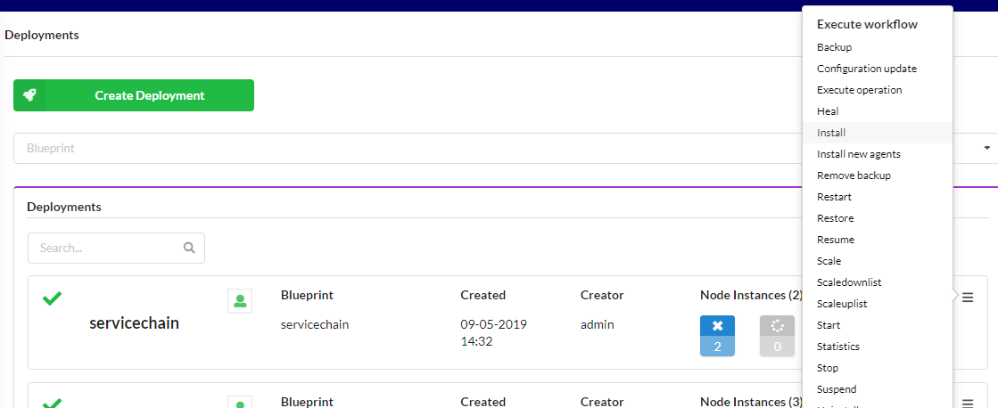
From the “Deployments” page in the Cloudify Management Console, select the “install” workflow from the right dropdown hamburger menu on the ‘service-base-network’ deployment.

This will display the install workflow dialog box. Press the “Execute” button to begin the installation. This will render the base network on the target cloud. Wait for successful completion before continuing.
VNF Provisioning - Fortigate Firewall
Now that the network substrate is in place, we can install our service VNFs. In this step we will be using a blueprint to deploy a Fortigate firewall.
Upload the VNF blueprint package
Using the Cloudify Management Console from the “Local Blueprints” page, select the “Upload” button.
This will display the “Upload blueprint“ dialog. In the upload dialog, use the following entries:
- Blueprint package: https://github.com/cloudify-community/blueprint-examples/releases/download/latest/network-automation-example-fortigate.zip
- Blueprint YAML File:
- For Openstack: openstack.yaml
- For Azure: azure.yaml
- Blueprint name: firewall
Once these fields have been entered, press the “Upload” button to copy the blueprint to the Cloudify Manager.
Create the firewall VNF deployment
Uploading the blueprint placed it in the Cloudify Manager local repository. In order to run workflows ( e.g. “install” ) on the blueprint, you must create a deployment, which represents the blueprint and any input parameters.
Prior to creating the deployment, a secret must be created that contains the Fortigate license file contents. The secret should be created with the following command:
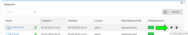
docker exec -i cfy_manager_local cfy secret create fortigate_license -f <path to your license file>From the “Local blueprints” page on the Cloudify Management Console, click the rocket ship icon on the “firewall” blueprint line:
This will display the “Create deployment” dialog box. Enter ‘firewall’ for the deployment name field. The rest of the default inputs will work as is. Press the Deploy button to create the deployment.
Install the firewall
From the “Deployments” page in the Cloudify Management Console, select the “install” workflow from the right dropdown hamburger menu on the ‘firewall’ deployment:
This will display the install workflow dialog box. Press the “Execute” button to begin the installation. This will instantiate the firewall on the target cloud. Wait for successful completion before continuing.
VNF Provisioning - Big IP Load Balancer
In this step we will be using Cloudify’s’ VNF provisioning blueprint to deploy an F5 Big IP Load balancer.
Upload the VNF blueprint package
Using the Cloudify Management Console from the “Local Blueprints” page, select the “Upload” button
This will display the “Upload blueprint“ dialog. In the upload dialog, use the following entries:
- Blueprint package: https://github.com/cloudify-community/blueprint-examples/releases/download/latest/network-automation-example-bigip.zip
- Blueprint YAML File:
- For Openstack: openstack.yaml
- For Azure: azure.yaml
- Blueprint name: loadbalancer
Once these fields have been entered, press the “Upload” button to copy the blueprint to the Cloudify Manager.
Create the load balancer VNF deployment
Uploading the blueprint placed it in the Cloudify Manager local repository. In order to run workflows ( e.g. “install” ) on the blueprint, you must create a deployment, which represents the blueprint and any input parameters.
From the “Local blueprints” page on the Cloudify Management Console, click the rocket ship icon on the “firewall” blueprint line:
This will display the “Create deployment” dialog box. Enter ‘loadbalancer’ for the deployment name field. The default inputs will work as is. Press the Deploy button to create the deployment.
Install the load balancer
From the “Deployments” page in the Cloudify Management Console, select the “install” workflow from the right dropdown hamburger menu on the ‘loadbalancer’ deployment:
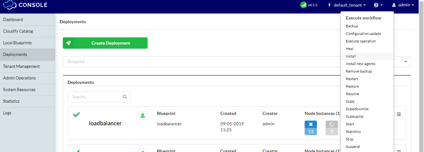
This will display the install workflow dialog box. Press the “Execute” button to begin the installation. This will instantiate the firewall on the target cloud. Wait for successful completion before continuing.
VNF Configuration
Both VNFs, firewall and load balancer, have been created on the target cloud. This step will configure them using blueprints.
Configure the Firewall
Upload the firewall configuration blueprint package
Using the Cloudify Management Console from the “Local Blueprints” page, select the “Upload” button
This will display the “Upload blueprint“ dialog. In the upload dialog, use the following entries:
- Blueprint package: https://github.com/cloudify-community/blueprint-examples/releases/download/latest/network-automation-example-fortigate.zip
- Blueprint YAML File:
- For Openstack: openstackapp.yaml
- For Azure: azureapp.yaml
- Blueprint name: firewallconfig
Once these fields have been entered, press the “Upload” button to copy the blueprint to the Cloudify Manager.
Create the firewall configuration deployment
Uploading the blueprint placed it in the Cloudify Manager local repository. In order to run workflows ( e.g. “install” ) on the blueprint, you must create a deployment, which represents the blueprint and any input parameters.
From the “Local blueprints” page on the Cloudify Management Console, click the rocket ship icon on the “firewallconifg” blueprint line:
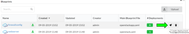
This will display the “Create deployment” dialog box. Enter ‘firewallconfig’ for the deployment name field. For the ‘fortigate_vm_deployment_name’ input, use ‘firewall’. Press the Deploy button to create the deployment.
Install the firewall configuration
From the “Deployments” page in the Cloudify Management Console, select the “install” workflow from the right dropdown hamburger menu on the ‘firewallconfig’ deployment:
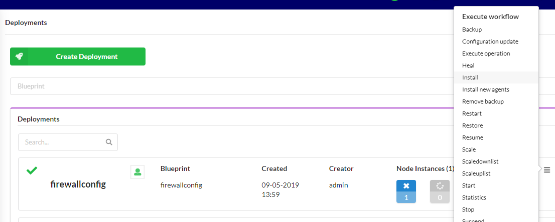
This will display the install workflow dialog box. Press the “Execute” button to begin the installation. This will configure the firewall. Wait for successful completion before continuing.
Configure the Load balancer
Upload the load balancer configuration blueprint package
Using the Cloudify Management Console from the “Local Blueprints” page, select the “Upload” button
This will display the “Upload blueprint“ dialog. In the upload dialog, use the following entries:
- Blueprint package: https://github.com/cloudify-community/blueprint-examples/releases/download/latest/network-automation-example-bigip.zip
- Blueprint YAML File:
- For Openstack: openstackapp.yaml
- For Azure: azureapp.yaml
- Blueprint name: loadbalancerconfig
Once these fields have been entered, press the “Upload” button to copy the blueprint to the Cloudify Manager.
Create the load balancer configuration deployment
Uploading the blueprint placed it in the Cloudify Manager local repository. In order to run workflows ( e.g. “install” ) on the blueprint, you must create a deployment, which represents the blueprint and any input parameters.
Prior to creating the deployment, a secret must be created that contains the Big IP license file contents. The secret should be created with the following command:
docker exec -i cfy_manager_local cfy secret create bigip_license -f
From the “Local blueprints” page on the Cloudify Management Console, click the rocket ship icon on the “loadbalancerconifg” blueprint line:
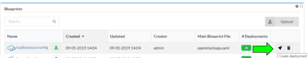
This will display the “Create deployment” dialog box. Enter ‘loadbalancerconfig’ for the deployment name field. For the ‘prov_deployment_name’ input, use ‘loadbalancer’. Press the Deploy button to create the deployment.
Install the load balancer configuration
From the “Deployments” page in the Cloudify Management Console, select the “install” workflow from the right dropdown hamburger menu on the ‘loadbalancerconfig’ deployment:
This will display the install workflow dialog box. Press the “Execute” button to begin the installation. This will configure the load balancer. Wait for successful completion before continuing.
Web Server Provisioning and configuration
The web server represents the target of the service chain.
Upload the HTTPD blueprint package
Using the Cloudify Management Console from the “Local Blueprints” page, select the “Upload” button.
This will display the “Upload blueprint“ dialog. In the upload dialog, use the following entries:
- Blueprint package: https://github.com/cloudify-community/blueprint-examples/releases/download/latest/network-automation-example-httpd.zip
- Blueprint YAML File:
- For Openstack: openstack.yaml
- For Azure: azure.yaml
- Blueprint name: webserver
Once these fields have been entered, press the “Upload” button to copy the blueprint to the Cloudify Manager.
Create the web server deployment
Uploading the blueprint placed it in the Cloudify Manager local repository. In order to run workflows ( e.g. “install” ) on the blueprint, you must create a deployment, which represents the blueprint and any input parameters.
From the “Local blueprints” page on the Cloudify Management Console, click the rocket ship icon on the “webserver” blueprint line:
This will display the “Create deployment” dialog box. Enter ‘webserver’ for the deployment name field. The rest of the default inputs will work as is. Press the Deploy button to create the deployment.
Install the web server
From the “Deployments” page in the Cloudify Management Console, select the “install” workflow from the right dropdown hamburger menu on the ‘webserver’ deployment:
This will display the install workflow dialog box. Press the “Execute” button to begin the installation. This will instantiate the web server on the target cloud. Wait for successful completion before continuing.
Web Server Configuration
Upload the HTTPD blueprint package
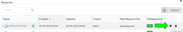
Using the Cloudify Management Console from the “Local Blueprints” page, select the “Upload” button.
This will display the “Upload blueprint“ dialog. In the upload dialog, use the following entries:
- Blueprint package: https://github.com/cloudify-community/blueprint-examples/releases/download/latest/network-automation-example-httpd.zip
- Blueprint YAML File:
- For Openstack: openstackapp.yaml
- For Azure: azureapp.yaml
- Blueprint name: webserverconfig
Once these fields have been entered, press the “Upload” button to copy the blueprint to the Cloudify Manager.
Note that the best practice is to have the configuration step independent from platform specifics. This will be fixed in a future release.
Create the web server configuration deployment
Uploading the blueprint placed it in the Cloudify Manager local repository. In order to run workflows ( e.g. “install” ) on the blueprint, you must create a deployment, which represents the blueprint and any input parameters.
From the “Local blueprints” page on the Cloudify Management Console, click the rocket ship icon on the “webserveconfig” blueprint line:
This will display the “Create deployment” dialog box. Enter ‘webserverconfig’ for the deployment name field. For the “httpd_vm_deployment_name”, enter ‘webserver’. Press the Deploy button to create the deployment.
Install the web server configuration
From the “Deployments” page in the Cloudify Management Console, select the “install” workflow from the right dropdown hamburger menu on the ‘webserverconfig’ deployment:
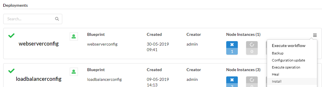
This will display the install workflow dialog box. Press the “Execute” button to begin the installation. This will start the web server on the web server VM. Wait for successful completion before continuing.
Service chaining
Now all the service ingredients are in place. The base network, the VNFs, and the target web server. This step will create the service chain that ties them together. The chain is described in a blueprint that references the previously installed blueprints.
Upload the service chaining blueprint package
Using the Cloudify Management Console from the “Local Blueprints” page, select the “Upload” button
This will display the “Upload blueprint“ dialog. In the upload dialog, use the following entries:
- Blueprint package: https://github.com/cloudify-community/blueprint-examples/releases/download/latest/network-automation-example-service.zip
- Blueprint YAML File:
- For Openstack: openstack_service.yaml
- For Azure: azure_service.yaml
- Blueprint name: servicechain
Once these fields have been entered, press the “Upload” button to copy the blueprint to the Cloudify Manager.
Create the service chain deployment
Uploading the blueprint placed it in the Cloudify Manager local repository. In order to run workflows ( e.g. “install” ) on the blueprint, you must create a deployment, which represents the blueprint and any input parameters.
From the “Local blueprints” page on the Cloudify Management Console, click the rocket ship icon on the “servicechain” blueprint line:
This will display the “Create deployment” dialog box. Enter ‘servicechain’ for the deployment name field. For the ‘f5_prov_deployment_name’ input, use ‘loadbalancer’. For the ‘fg_prov_deployment_name’ enter ‘firewall’. For the ‘httpd_prov_deployment_name’ input, enter ‘httpd’. Press the Deploy button to create the deployment.
Install the firewall configuration
From the “Deployments” page in the Cloudify Management Console, select the “install” workflow from the right dropdown hamburger menu on the ‘servicechain’ deployment:
This will display the install workflow dialog box. Press the “Execute” button to begin the installation. This will configure the service chain. Wait for successful completion before continuing.
Conclusion
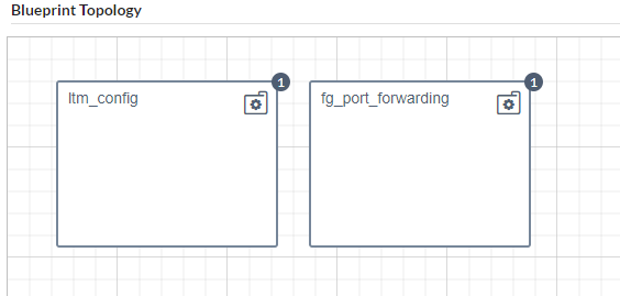
Through the series of blueprint installations a service chain of connected network services (Load Balancer, Firewall and Web Server) has been created. In this case service chaining consists of a port forwarding rule on Fortigate and load balancing rule on BIG IP in order to pass traffic through. While technically possible to orchestrate the various solution components in many ways, the layered approach is a best practice because it provides:
- Isolation - the layers represent domains of orchestration with a common lifecycle
- Abstraction - lower layers can be abstracted from higher layers, increasing reusability
- Granularity - each blueprint represents an orchestration specialty that can be versioned and evolved independently by different teams.
running a single end-to-end example
Through the series of blueprint installations been executed, a composed scenario been created. This composition is also supported by a single pane of glass service
Check out the latest version of the network automation example in our Examples bundle.
- Use the above link and upload as new blueprint
- Choose main YAML file as your infrastructure- Openstack or Azure
- Deploy a new service from the e2e blueprint and run “Install” workflow.
- Note that the last deployment (the service chain) is not executed and is left for you as manual step to experience Cloudify operation